
Thank You and see You soon!
I would like to thank all of my supporters for sticking with me, particularly the folks who supported during the last weeks when everything seemed already over and done.
I will repost this idea to see what becomes of it. Maybe we'll meet again?
Mr_Kleinstein
Let's Face It!
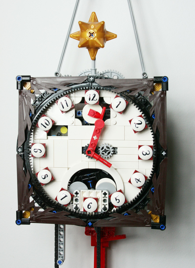
There have been many among you who asked me for a clock case, or at leat a dial or clock face to cover up the gears. The gears in my head thus went tick tock, and out came this solution. The clock face is two plates thick wherever allowed, and can be installed instead of the golden greebles. I still haven't come up with a decent case, though...
I have created a video which displays the clock in its new garment. The video also shows how the clock is set. One of the minor improvements I made to the mechanism is an adjustment for evenness of the tick-tock, so the working of the escapement may be optimized without having to shift the clock sideways. So if you are going to make this a grandfather clock, fire away!
The video is on my flickr stream, in the respective album with all the pictures to the Wall Clock.
Have a good time!
Mr_Kleinstein
Inner Workings Vol. II
The update continues... with the gear arrangement from big hand to small hand. If you haven't done so, I suggest you start reading with the last update, which unfortunately is to be found below this one - scroll down for Vol. I!

The required gear ratio from nimutes to hours (from big hand to small hand) is 1:12. The challenge was to make that drive coaxial, so both hands share a common clock face, like we have come to expect from a proper clock. It was actually the first gear module I designed for this project, right after the new worm gear came out. It's a little larger in diameter than the old 2 stud-wide worm gear, and it meshes with the 12-tooth gear. The pair of the make a nice 1:12 ratio, so all I had to do was to create a coaxial arrangement. It is shown in orange.

The 24 hrs daylight disc is derived ftom the minutes shaft, which drives the big hand, by a 1:24 division. Another worm gear is used in there, together with a 24-tooth. The moon phase dial is driven from the very same axle, with an additional division by 60 via another worm gear and a large turntable - the display will show two full moon cycles on one revolution of the turntable. The moon phase is thus approximated as a 30 day-period. The precise value is about 29.4 days. This is why we have a "gap year" every four years, to make up for that difference. The fastest-moving element in the Wall clock is thus the escapement wheel, at one revolution every 16 seconds. The slowest-moving part is the moon phase dial, at one full revolution every 60 days.

The self-winder was my way of overcoming the inherent limitations of Lego clock making, markedly the relatively high friction involved in every movement. The situation is aggravated by the limited set of gears available, which increases the numer of turning axles needed. I simply ran into a limit of how long I could make a weight-driven clock run without having to wind up. Without smashing a hole in the floor to make room for the weight to go deeper down, or resorting to a very heavy, non-Lego weight (which anyway tends to warp the whole structure in no good way), I never got past a few hours of running time. Having the clock wind itself was my way out. I simply used the battery box as weight, attached it to an endless chain, and added a motor and switch. When the weight has travelled downwards into the loop of the chain, the motor makes the assemply climb back up to the top. It's as easy as that! This has given me a full autonomy of several months, in which I didn't have to supply any external power to the Wall Clock. Cool, huh?
Hope you enjoyed reading this, and thank you for your time!
Mr_Kleinstein
Inner Workings Revealed
As promised, I will take you on a tour of the clockwork mechanism behind my Wall Clock.
It has a lot to do with ratios. The ratios of seconds to minutes, minutes to hours, hours to day, and days to moon cycles had to be replicated with gear ratios. The first ratio that concerns us is the ratio of the tick-tock. This clock goes tick in one second and tock in the next. This is called a "true second tick", because you get exactly one tick per second, and the seconds hand will also move in steps of full seconds, precisely one per second. I found the true second tick makes it easy to compare the precision of the Wall Clock to a radio-controlled analogue clock by listening to the "beat" of the two ticks. If they don't noticeably drift apart within one minute, the clock will not be wrong for more than a few minutes per day.

Now let's look at the escapement. That is the mechanism transferring the power from the drive train to the pendulum, so it won't stop swinging, and at the same time transferring - in opposite direction - the timing from the pendulum to the clockwork. It's the nexus of the whole system. In the picture above, the escapement elements are shown in red. The eight-toothed propellor element figures as the escapement wheel, and the torque applied from the drive train tends to make it turn. The two bionicle teeth on the fork-like strukture make up the anchor pallets, which stop the escapement wheel from freely turning. The spacing of the pallets is adjusted so that the escapement wheel will just pass with either one tooth in between them without getting stuck. The escapement wheel will then make contact with either pallet vice versa, stopping there, until the pendulum - which is, of course, linked to the anchor, swings back in the opposite direction. When the escapement wheel makes contact with the anchor pallets, it gives them a little push that provides enough energy to overcome the friction within the pendulum system.
Having a low-friction pendulum is one of the key requirements in making a Lego clock. When I first designed a clockwork, pendulum and anchor were one assembly, suspended on a Technic axle. Friction was very high, because the weight of the pendulum and pendulum bob all acted on that one Technic axle bearing. The clock could only be kept working by a high-torque powering system, which meant a very short running time before the next wind-up. I changed the design by separating anchor and pendulum bearing, and installed a slightly flexible link in between the two. The anchor still rests (or rather swivels) on Technic axles, but it is a very light-weight structure that has little friction. The much heavier pendulum received a knife-edge bearing, which is almost free from friction. There is, however, still air friction involved - the pendulum is about one meter long!

Now, where does the drivig power come from? The Wall Clock is weight-driven. That means, a somewhat heavy weight is pulling on a chain, which is going around a sprocket. I made the chain an endless one, the reason for which will become apparent when we talk about the self-winder, which doubles as the weight. The advantage of weight-drive opposed to spring-drive lies in the fact that a weight will always pull with constant force, while a spring's force becomes lower and lower while the spring runs down. That makes matters much, much more complicated when you want to build a precision timepiece.
For now, let's follow the force, which is strongest at the point where the chain enters the gear block. All the gears involved in transferring motive power to the escapement wheel are shown in green (above). Unlike other places in the clockwork, the specific gear ratios are not exactly critical. Let's say that the seconds shaft, which revolves precisely once every minute, is powered from the first shaft, which revolves about once every 20 minutes. With that 16-tooth sprocket on the first shaft in mesh with the chain, the chain (and thus the weight) falls about one chain link in 2 min 40 secs.
The power is, however, divided by the same ratio with which the speed is multiplied, and that's not taking into account bearing friction. That means the torque provided to the actual clockwork at the seconds shaft is less than one twentieth of the torque provided by the weight. The figure will still get worse when we get closer to the escapement wheel, which is the fastest-turning element in the system (this is why a slow-running escapement wheel with many teeth is more efficient than, say, a single-pin escapement).

Let's look at the path from the escapement to the seconds shaft (shown in yellow). When the clock goes tick every second, and the escapement wheel has eight teeth, it will go round in exactly 16 seconds. So we need to interface that to the seconds shaft, which must go round in 60 seconds. 16:60 is not really an applicable gear ratio in Lego; neither is 8:30. So now we're getting into combined ratios of gears which weren't really designed to mesh. I went for 16:40 and 16:24, which equals 16:60. The bearings of the 4 stud-axle with the 40-tooth and the 16-tooth gear had to be mounted with offset to the grid for that purpose.

The way from seconds to minutes is somewhat tricky - not just because of the gear ratios involved, but also because of the spacial arrangment of the whole clockwork. Some gears are employed to transfer the motion without changing ratios. They're in fact "idler gears". The gear train from seconds to minutes is shown in blue. The necessary ratio is, obviously, 1:60. The prime factors of 60 are 2, 2, 3, and 5. 1:3 and 1:5 can be easily achieved with Lego, 1:2 and 1:4 are harder, because they don't fit into the grid. I used a set of gears consisting of 12:36 (1:3), 12:24 (1:2), 12:24 (1:2), and 8:40 (1:5). After that, there are some idler gears wich bring the motion to the big hand, which is located on, but not connected to, the central shaft. The big hand is mounted on a clutch gear with pin hole. In one of the shafts I included a friction coupling, which permits the clock to be set without having to take apart the clockwork.
Announcement: It appears like the character limit for one update is reached. I'll have to explain the rest in another update!
Mr_Kleinstein
First Battery Change
After more than three months of continuous operation, the batteries of my Wall Clock had finally run down. The battery box has been turned on all the time, as was indicated by the green light on it. The clock has rewound itself about every two hours over those three months.
It has only stopped three times, and I know that in at least two of these three instances it had been touched, because it wasn't hanging level on the wall anymore (I have made pencil marks to check that). That might be due to my kids playing in the kitchen, or maybe to the cleanlady who's doing a thorough job vacuuming.
To me, this is actually the most amazing fact: Everything, every plastic part, is still properly working without need for repairs, without any visible wear and tear, and within the same accuracy of about 2 minutes a day. Accuracy is very much dependent on the clock hanging absolutely still, straight and level.
There is a friction mechanism in the gears that allows me to set the clock simply by moving the big hand. The clock doesn't have to be stopped or taken apart for that. On the rear, there are two additional knobs for adjusting the daylight and moon phase displays, but they don't need attention if set properly.Well, just like a real clock, you know?
Mr_Kleinstein
PS: Stay tuned, I'm preparing an update that is going to explain the inner workings of the mechanism!
Expired
Leave Private Feedback
This will only be visible to the creator.


